How to Replaces BMS PCB board to Fix Ryobi Battery – 1337
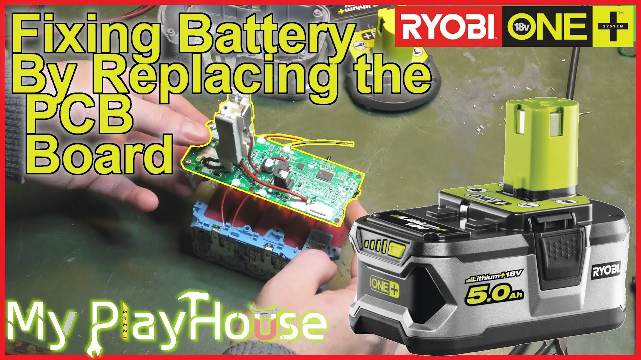
I manage to fix this Ryobi 5Ah battery, by replacing the PCB,, circuit board.
Managed to get this new board at at a price of just $8-ish.
Most non charging Ryobi batteries, does not need this, and can be relieved by charging them a little bit directly on the cells. As I show in this video : https://youtu.be/aM_HhjdVpwU or this one : https://youtu.be/2xWyzFDSjRg
[Affiliate Links]
Link CN – Battery Charging Protection Circuit Board PCB for Ryobi 20V P108 RB18L40 Power Tools Battery : https://s.click.aliexpress.com/e/_DCdkV2r
Link US – Not the same as the one I used,, but might work,, but expensive : https://amzn.to/4a0Sj50
Link UK – Very similarly to the one I installed, but a little different looking : https://amzn.to/3uDc2ao
___________________________________________________________________________________________________
http://www.patreon.com/myplayhouse
For 3$ a month, you get an extra weekly “What’s UP” update video. Just for my Patrons. The Support I resave on patreon is all used on stuff to make interesting videos on YouTube.
My PlayHouse is a channel where i will show, what i am working on. I have this house, it is 168 Square Meters / 1808.3ft² and it is full, of half-finished projects.
I love working with heating, insulation, Servers, computers, Datacenter, green power, alternative energy, solar, wind and more. It all costs, but I’m trying to get the most out of my money, and my time.
how to repair windows 7


Hi Morten, yes, there is a certain order for disconnecting/connecting the BMS, in laptop batteries the common one is disconnected first + then all contacts as the voltage decreases, the common one is disconnected last – the connection is strictly in the reverse order. The BMS battery board in the video may have remembered the error and went into blocking mode, perhaps it can be brought back to life with a programmer.
Awesome that you got it working! And testing it with a drill similar to my own. My other 5Ah batterties have been used a lot with my chainsaw recently. I hope you get a lot of use out of that one. /Jonas
The order of connecting the BMS terminals was posted online elsewhere, here is copy and paste of that.
It is very tempting to connect +Ve and -ve first since those are the hardest to connect, but dont.
I connect the -ve first, then the bms wires 3.7v, and up.
Finally I connect the +ve.
Edit: found the next two paragraphs online, they explain T1.
T1 is a Test terminal that is used by the charger to determine if the pack is okay—if the FETs are off then the pack will fail this test and the charger blinks the defective led pattern. The FETs connect the terminal labelled (-) to the bottom of cell 1.
The charger and the pack send a secret code back and forth on T1; without it the pack won't charge, and the charger won't work either.
=====
My original post follows, which seems to not be correct.
I think that T1 terminal might have something to do with temperature sensing – but what it does and how it does what it does, those I can’t answer.
Hey Morten. Do you have any idea on where I can get those metal springs to push out the mounting clips on the side of the battery… I lost min, and fundt them ones. But didn't save a link.. Me sad now 😋
Morton, you did an awsome job, and we al learned allot from you. Tx for the vids!
second
first