Media Access Control Addresses (MAC) – Ethernet Frame structure
PDF Download Link: https://tinyurl.com/rwlvuub
or http://en.videolearner.com/index.php/computer-networks/9-computer-networks-chapter-02/18-14-media-access-control-addresses-mac-ethernet-frame-structure
Media Access Control Addresses (MAC) – Ethernet Frame structure
Computers Networks
Each node on an Ethernet network has a physical address or Hardware Address
to uniquely recognize it throughout the network.
Also referred to as Media Address Control -MAC Address.
It is a 48 bits binary number
and is written in the hexadecimal arithmetic
as six two-digit hexadecimal numbers separated by dashes (in windows) or with dots (in unix / linux).
One such address is 74: ea: 3a: cd: 06: 40.
On a computer equipped with an adapter / network card,
the MAC address is a feature of the network card
and sometimes written on it by the manufacturer.
It can be FOUND with the appropriate operating system command (ipconfig / all windows, ifconfig Linux, etc.)
Nodes of an Ethernet network
exchange data-information
which they encapsulate in packages
which are called frames.
In the header of the frame administrative informations are placed
of which the most important are the addresses sender (source) and recipient (destination).
MAC addresses consist of two parts of the 24 bit.
The first part, which is called OUI – Organizational Unique Identifier is administered by
Institute of Electrical and Electronic Engineers (IEEE)
and is available exclusively to the hardware manufacturer.
The second part identifies the hardware manufacturer on his own responsibility.
In the first part, two digits are of particular importance.
The figure below, shows the structure of a MAC address on Ethernet.
Note that the most important byte MSB-Most Significant Byte is sent to Ethernet first,
but for each byte, the least significant bit -LSB first.
This way of sending, is called Little Endian at a byte level.
Thus, when transmitting digits of an Ethernet address, they will be sent, at byte level,
first MSB, for our example 74 (0111 0100)
but in the reverse order :0010 1110, first b0, then b1 and so on.
These first two bits, which are essentially b0 and b1 of the address MSB, are of particular importance.
The first (b0) is the M (multicast) bit or l / G (Individual / Group).
When it is 1 it means that the address refers to many recipients,
is multicast, otherwise it concerns a specific recipient.
The second (b1) is the X bit or U / L (Universal / Local).
When it is 1 means that the address is locally managed(is assigned to a device by the network administrator,
leaving the embedded address.Locally attributed addresses do not contain OUIs.)
otherwise when 0 is universally unique.
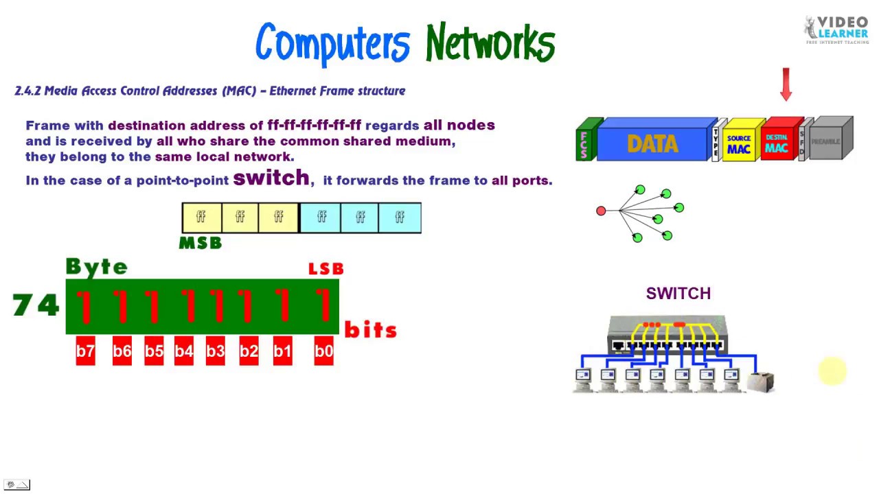
A special case is the address with all digits 1, ff-ff-ff-ff-ff-ff which is the Broadcast address.
Frame with destination address of ff-ff-ff-ff-ff-ff regards all nodes
and is received by all who share the common shared medium,
they belong to the same local network.
In the case of a point-to-point switch, it forwards the frame to all ports.
Ethernet Frame has a specific structure as shown below.
To make it easier for the receiver to synchronize with the transmitter, starts with a preamble
seven bytes of alternating aces and zeroes (0x55)
and a 0xD5 byte which marks the Start Frame Delimiter –SFD .
After that are the addresses of the six bytes, each,
first destination address
so that the recipient can be activated in a timely manner.
and then sender’s address .
Then the two bytes field “Type / Data Length”
specifies the type of data that the frame transfers
or which higher-level protocol are concerned.
If it has a value of less than 1500 (0x5DC) then it indicates the length of the data it carries.
At the end it includes four bytes
the Frame Check Sequence (FCS)
according to the CRC-32 algorithm
so that it can be identified by the recipient any error occurs during transmission.
After the end of the frame, there is a 96-bit pause period
to allow the receiver circuits to process the received frame
and be ready to receive the next frame.
This is called InterPacketGap (IPG).
The length of the data payload of the frame load can reach from 46 to 1500 bytes
and is called MTU- Maximum Transmission Unit.
It is the requirement of the standard overall frame size
not be less than 64 bytes (18 header and 46 load).
If it happens to be smaller then it is usually filled with zeros (padding) to reach the minimum length.
SPYROS ZYGOURIS
videolearner.com FREE INTERNET TEACHING
VISUALISED COURSES
mac address


