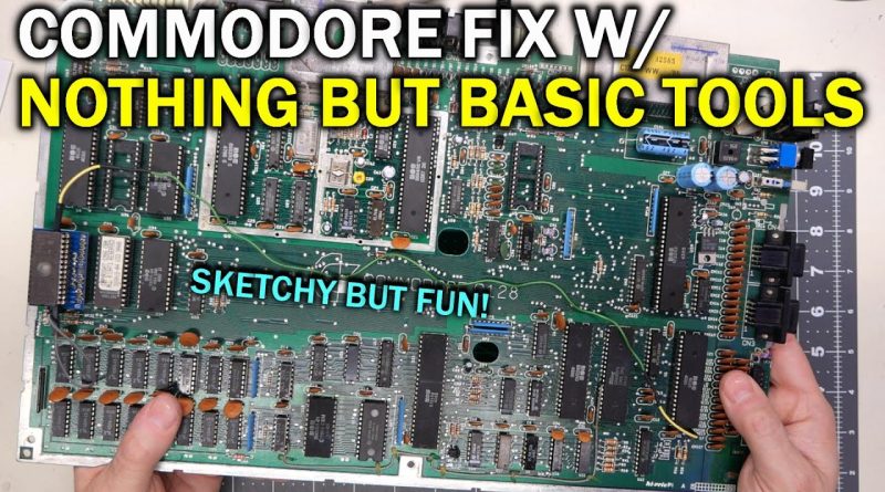
You don't always need fancy tools to fix a broken 8-bit computer
I’m going to fix this 8-bit computer with no special Commodore test tools, no oscilloscope and no expensive desoldering tools.
— Video Links
C128 Schematics:
https://www.zimmers.net/anonftp/pub/cbm/schematics/computers/c128/
C128 RAM Map:
https://www.cubic.org/~doj/c64/mapping128.pdf
Adrian’s Digital Basement Merch store:
https://my-store-c82bd2-2.creator-spring.com/
Support the channel on Patreon:
https://www.patreon.com/adriansdigitalbasement
Adrian’s Digital Basement (Main Channel)
https://www.youtube.com/channel/UCE5dIscvDxrb7CD5uiJJOiw
My GitHub repository:
https://github.com/misterblack1?tab=repositories
— Tools
Deoxit D5:
https://amzn.to/2VvOKy1
http://store.caig.com/s.nl/it.A/id.1602/.f
O-Ring Pick Set: (I use these to lift chips off boards)
https://amzn.to/3a9x54J
Elenco Electronics LP-560 Logic Probe:
https://amzn.to/2VrT5lW
Hakko FR301 Desoldering Iron:
https://amzn.to/2ye6xC0
Rigol DS1054Z Four Channel Oscilloscope:
https://www.rigolna.com/products/digital-oscilloscopes/1000z/
Head Worn Magnifying Goggles / Dual Lens Flip-In Head Magnifier:
https://amzn.to/3adRbuy
TL866II Plus Chip Tester and EPROM programmer: (The MiniPro)
https://amzn.to/2wG4tlP
https://www.aliexpress.com/item/33000308958.html
TS100 Soldering Iron:
https://amzn.to/2K36dJ5
https://www.ebay.com/itm/TS100-65W-MINI-Digital-OLED-Programmable-Soldering-Iron-Anti-static-Structure/113382669853
EEVBlog 121GW Multimeter:
https://www.eevblog.com/product/121gw/
DSLogic Basic Logic Analyzer:
https://amzn.to/2RDSDQw
https://www.ebay.com/itm/USB-Logic-DSLogic-Basic-Analyzer-16Ch-100MHz-4Ch-400MHz-Xilinx-Spartan-6-FPGA/202543965672
Magnetic Screw Holder:
https://amzn.to/3b8LOhG
https://www.harborfreight.com/4-inch-magnetic-parts-tray-90566.html
Universal ZIP sockets: (clones, used on my ZIF-64 test machine)
https://www.ebay.com/itm/14-16-18-20-24-28-32-40-pin-IC-Test-Universal-ZIF-Socket-Fs/303206721971
RetroTink 2X Upconverter: (to hook up something like a C64 to HDMI)
http://www.retrotink.com/
Plato (Clone) Side Cutters: (order five)
https://www.ebay.com/itm/1-2-5-10PCS-Micro-Scissor-125mm-PLATO-170-Electronics-Cutter-Side-Cutting-Pliers/163458746184
Heat Sinks:
https://www.aliexpress.com/item/32537183709.html
Little squeezy bottles: (available elsewhere too)
https://amzn.to/3b8LOOI
— Instructional videos
My video on damage-free chip removal:
— Music
Intro music and other tracks by:
Nathan Divino
@itsnathandivino
how to repair windows 7


A brilliant tip on how to find faulty ram chip. With this method you don't even need the PDF or the book. You just put a good ram chip on every single ram chip on the board one at a time. The worst case scenario is you have to do it 16 times to find the faulty ram. So 4 to 8 minutes should do it. But it would be a very short video. I use to be a TV engineer many years ago and one of my friends Welly use to repair a lot of 8 bit computers and can remember him constantly replacing ram chips and putting in sockets. Ho for the good old days 🙂
The existing MMU version cannot take more than 128 of RAM; the MMU CR bit 7 is reserved and has no effect on memory manangement on existing MMUs.
Bank 1 can be tested by running the C64 mode in Bank 1.
monitor
monitor
pc sr ac xr yr sp
; fb000 00 00 00 00 f8
m1c00
>01c00 00 0b 1c 0a 00 9e 37 31
>01c08 38 31 00 00 00 78 a9 3e
>01c10 8d 00 ff a9 06 8d 06 d5
>01c18 a9 7e 8d 00 ff a2 26 bd
>01c20 2b 1c 9d 00 38 ca 10 f7
>01c28 4c 00 38 a9 40 8d 06 d5
>01c30 a2 01 8e 0a d5 8e 09 d5
>01c38 8e 08 d5 ca 8e 07 d5 8e
>01c40 30 d0 a9 e3 85 01 a9 2f
>01c48 85 00 a9 f7 8d 05 d5 6c
>01c50 fc ff
s "b1c64mode",8,1c01,1c52
saving b1c64mode
ASCII is a 7-bit standard; the Apple II uses ASCII for the lower 128 character slots.
It's the Atari and Commodore machines that don't.
Try to keep a Windows version in your labor, that is activated and has a legal mot broken code, and its dvd. You can use a satellite for free to fix just about anything, except stolen goods or those, that has debt on its shopping price. The fix goes with some retries, and is arranged in order. For example, the Asus laptop is first, then the phone, the 286 is the last. A fix may take a month, or just few minutes.
Thank you for this!I have 3 C64s and none of them output anything to the screen… 🙁 Do you have any troubleshooting ideas on this?
PiggyBack mounting chips is very common. I used it to expand memory on my AcornAtom, just keep the ChipSelect out as these has to go to the bank select chip.
Yes, it's slightly cringe, but it works..
Hello Adrian,
Thanks for your videos. This one reminds me of my very first job, when I started working as a technician, which I really wasn’t yet. I had to manage a small technical service focused on repairs, working by myself as an early beginner in such a job. 😉
I was lucky because all the real technicians who preceded me in that lab had left the small company just a short time before I applied there. Therefore, I was hired urgently to repair, or more often try to repair, the numerous malfunctioning devices that were stacked in that abandoned technical lab. The situation was so urgent that they probably would have even hired a confectioner or a pastry chef to fill the position. LOL
The trick you showed us about piggybacking confused me a lot the day I first saw such a piggyback in a C64 that had been previously repaired when the real technicians were still on deck. This led me to investigate why this could work. I learned a lot of interesting things while I had this job, and perhaps I should have stayed focused on hardware repairs instead of leaving this job to join a software design position after a few years in this iconic lab in my memories.
This is why I always have a great time when I watch your videos, and moreover, as a French speaker, they help me recall my school knowledge of English.
Thanks a lot, Adrian!
Seeing as MT (Micron Technology) RAM supposedly fails because they don't have much tolerance for overvolting due to elderly psus, is it worthwhile checking the PSU for issues if the faulty C64/128 came with it?
If there’s Micron RAM in a machine, you 99% know what the problem is even without turning on the machine 😉
Between snipping the wrong legs and installing upside down, it really wasn't your day! (I hate those days!)
The dance party was the minute of silence for the broken RAM IC.
I was disappointed to find that 'basic tools' aren't things like hammer, pliers, and a cheap screwdriver with 6 bits, 3 of which are useless, and a hacksaw.
If the RAM chips are empty (MT) there’s nothing inside; that’s why they go bad. Feed them to Rammy. 😊
Brilliantly explained yet again Adrian. Fantastic videos
Whilst over chip soldering might work, based on your previous videos I'd much rather just socket the chip and be done with it.
If the piggyback method doesn't work, you could use a resistor to pull up or down an address line (or some other line not shared by both banks) to see if the display changes to confirm what bank is being used for screen ram. Once you know the correct bank. you could try pulling down the data out on your suspect chip to confirm if it is actually the chip of the data bit you think it is that is wrong. You could try pulling down the data out on all the chips in your identified bank one by one if you don't have good schematics and you want to know which chip is which bit.
Excuse me Adrian, min 27 you piggyback the chip upside down !
"Spurious Zeros" is an excellent band name,
peace be upon you sir and zamzam water
ESD probably struck again! 😮
Those soldering irons are actually really nice.
I got a proper one that cost 3 times as much and I got my boyfriend one for his birthday one year, and I just end up using his all the time
As always, thanks for keeping the repairs fresh and interesting!
A book! My god, a book
I remember reading an article in 80 microcomputing (TRS-80 centric magazine) about how to add 16K to the base unit on the cheap. And it was basically what Adrian did here. You piggy backed the additional 8 4116 chips on the existing RAM chips, all except the CS pin which you bent up 180 degrees. Solder all the pins (except the CS line). Then run a bodge from chip to chip on the lifted CS lines, and then onto a pin on the address decoder chip, so that when you hit the second bank of 16 the piggy back chips were selected.
And the nice thing about that mod was if you ever got the expansion chassis, you could disable the additional on board ram by simply cutting the CS bodge wire.
Used have fun with uppercase space.
I'm sad the SID was missing and we couldn't have a dance party!
This is a "quickie"?? Do you realize how much trouble I get in when I tell my wife I'm just watching a short DIY video, and then suddenly an hour has gone by? Sleeping on the couch is getting very old, and it's all your fault!! (yes, I'm addicted to this channel…)
41:46 "I just wanted to demonstrate to do it with no damage and be safe about your repairs." And you failed, you cut a pin off the wrong chip.
25:48 did anyone else notice that all the chips are oriented as notch down, but Adrian put the piggy back chip on notch up, IE upside down.
I am actually glad to see you do this type of soldering. I have a few old computers where the PCB has damage and it's extremely easy to lift pads. For those boards, I prefer just cutting the old components out and resoldering the new component on top. It doesn't look pretty but seems to work fine.
ASCII is one thing, PETSCII is another thing, and the screen codes a third thing. Screen code 01 is 'a' or 'A'. Petscii 41hex is 'a' or 'A', C1hex 'A' in shifted mode.
4164 DRAM pin 2 is data input, so that could be left uncut. Pin 14 is data output.
Is it also good to cut the old chip’s VCC so the bad chip is no longer powered too?
you might want to cut the VCC and GND pins on the bad chip out so it would be unpowered and couldn't short OR pullup.
I would honestly recommend getting one of those cheap spring loaded desoldering tools and a heat source like a hair dryer or the like.
1. Cut all the legs on the chip.
2. Heat the board up with the hair dryer, focus on the local area where the work will take place. This will more or less make the copper layers inside less eager to soak away the heat from the iron.
3. Use the soldering iron to gently pull away the pin using a pair of tweezers.
4. After removing each pin, hold the tip of the iron at the "edge" of the pad, it is okay to be a bit over the soldered filled hole. And when heated, use the desoldering tool from the opposite side, and now you should have a perfectly clean empty hole ready for a new pin.
5. Rinse and repeat from step 3. Occasionally one can need to add some new warm air to the board.
6. Place in the new chip and if there is heavy grounding on the board, feel free to take aid from the hair dryer again.
Generally speaking, the excuse of "I don't have basic tools" isn't a good excuse for doing a hack job. When the basic tools in question are so cheap that most people don't even consider them a professional option.
Now yes, a proper desoldering station is way faster. But doesn't actually do the job better than if one has some patience. The 5$ solder sucker is honestly one of the best bang per buck tool one can get as far as soldering is concerned. And actually faster than a desoldering station if one only has to desolder 1-2 holes, since it doesn't need to heat up.
[8:26] Notice that although zeroes have popped in and out of existence on the screen, they are popping up at the same location every time. Like the one under the 'd' of 'all rights reserved'.
for fixing things on the cheap, i use a vaccum desoldering pump i bought at a local electronics store for 1-2 usd. heating up the chip legs from the top layer and using the pump on the bottom layer works wonders. one thing though is that you've got to be carefull with some boards, like PCChips mobos where traces lift very easily. i almost destroyed an M912 trying to replace the fake cache lmfao, had to add some bridges afterwards 🙁 .with a C64 board it does just great.
Now I want to see how you mod a 128 to have 256k on board. That will be a neat mod to do